You Just Brought an Old Radio Home
Web PDF • Imposed PDF• Raw TXT (OCR)

![RADIO-BUILDER’S HANDBOOK SCHEMATIC SYMBOLS USED IN RADIO Thie symbels below are standard in radio, TV and clectronics diagrams. curved wire crosover and dotted connection fs preferred. The symbol for & ground point may indicate actual connection 16 the métal chasis, or & cor i s el b S M e e RON CORE. °° ° Oa SWITCH ar CRYSTAL e | 4 e | 31 s gt ThansromeR | o\ o ruse —@— ruor e R s amssrons| I caneron mfiq ElecTroommame 4 ONE CELL OR Apwusrs — g | K F SR e e — T e 2= o P e A e | o o . [ 8= ] 2 2 o s [y L= oo ¥ 10](you-just-brought-an-old-radio-home-raymond-cady 10.png)
![| Chart of Radio Symbols — aewu g we O comecren | —4— A ? oo Silte | & | yacuum TUBES ohiEE - S| = 1922 — 1935 v :{wwcn Ty R * P crouno et chj; s, Ry cratobe | ¥ = SNGLE - + [ Two rement q xeo o B convENSER e aow | %] s SWITCH o s DETECTION | 4 r Coudinsi sovngmon| 2 Jo| B G | e “GANGED" (rmoper) | * o - screen N4 % coxorusea sarreaes e, (BER g Cremopes |20t PHONO —u Beeo | R coxe PICKUP / e | e cons — e |udoh w(v;\.ctn PHONOGRAPH "1’.::::‘ TRANSFORMER) | e - rf “ MAGNETIC g % [ v | & soven o pewrase AUDIO. OCTAL BASE SOCKET fi SR west | [ Amvan s A% ot = BcaliS FoR DETAILS OF CoNECrIONS Pusn-puLL e ™ =R ] | see MrRs. TUBE MANUALS Takns- ueso NEVER GUESS / e, s oo L FixeD posT TYPICAL MODERN TUBES W Jhcx GRIO. DIODE~ TRIODE YRR e secerma| —(@)— P B a0 MULTI-GRID TUBE e e % e aaios ane s 2 o (PoTenTI- vourmereR | @ | - [/ USUALLY BEING THAT Pty L S o](you-just-brought-an-old-radio-home-raymond-cady 12.png)

You Just Brought an Old Radio Home:
Now What Do You Do?
Raymond Cady
goldenageradiorestoration.com
Whether you are just beginning to collect antique radios or you have been at it for
a number of years, if you are thinking about doing more than just admiring your
radio, this article may be of some help to you.
We begin by taking a quick look at the steps involved in radio restoration, and
then get into a little more detail. Of course, an article like this could go on for
many pages on each topic, but this article introduces you to the overall approach
to take and goes into some detail.
Where to Begin
1. Carefully look over your radio both inside and out. Is everything there
including knobs and the chassis mounting hardware? If not, make a note of
what you must replace. These items all cost money and can help you to
value the radio you own or are considering purchasing.
2. Turn the knobs. Do the controls work? Is the volume or tone pot (a pot is a
potentiometer, basically a variable resistor) frozen or stiff? Does the dial
pointer move or does the tuning knob just turn without anything
happening? When testing it, don’t force a stuck pot to turn because you
can damage the control. Just note that you will have to fix it. (After you
remove the chassis later, you will spray them with contact cleaner and work
them gradually to clean them up.)
3. Is there a back on the radio? Should there be one there? If there should be
one and it is missing, you'll may want to consider reproducing it from
Masonite.
You Just Brought an Old Radio Home - Now What Do You Do?
Raymond Cady ~ GoldenAgeRadioRestoration.com cadyraymond1@gmail.com (405) 820-8014,
4. How about the antenna? If you can see it (sometimes it is inside on the
back of the back cover) does it look intact? Does it look as though all
windings are unbroken? A broken antenna winding usually requires
replacement of the antenna.
5. Is the power cord flexible or stiff? Has it been patched or spliced? If it’s not
in good condition, just cut it off now and throw it out. Put a new one on
later.
6. Look at the chassis while it's in the cabinet. Are there any tubes missing? If
50, again you'll have to spend money to replace them. Is there rust or a
dirty film on the chassis? If so, you'll need to clean off the rust or film. A
sticky smoker’s film is not unusual, but also not fun to clean off. Still, it has
to be done because leaving it there can cause overheating, not to mention
that it's nasty.
OK, you've looked it over, now you want to know if you can plug itin and give
it a tryout. If there is a power transformer in the radio then you absolutely
cannot power it on. You risk shorting out your transformer. If the radio is a
transformerless AC/DC type, you can power it on. If it doesn’t power up, you
may have a bad tube.
HINT: 1 power up AAS type radios to listen for signs of silver migration
disease in the IF transformers. This helps me plan my repairs.
Ensure You Have a Basic Understanding of How Radios Work
Before we start taking this radio apart, let’s take a minute and go through how
these radios actually work. It will really help your troubleshooting later if you
run into a problem. (See Figure 1.)
1. The first stage involves the antenna and tuning capacitor. Together they
form a resonant circuit that allows you to select an individual frequency
2)Page
You Just Brought an Old Radio Home - Now What Do You Do?
Raymond Cady ~ GoldenAgeRadioRestoration.com cadyraymond1@gmail.com (405) 820-8014,
from everything that s out there, This circuit creates a small
microvoltage current that is fed into the grid of the first tube in the
radio. This RF (radio frequency) tube amplifies the incoming signal.
2. Did you notice the second tuning capacitor next to the one for the
antenna? This capacitor is for the oscillator and is tuned to be the exact
IF frequency (such as 455kc) above the tuned frequency of the antenna
capacitor. This resonant circuit uses its own coils and tube or part of a
tube before being mixed with the RF signal. This mixing allows the magic
of heterodyning to occur. A weak RF frequency is mixed with a strong
oscillator frequency. The result is a strong signal at the IF frequency that
can be passed on the next stage in the radio. This signal processing can
all occur in one tube (the usual norm) or be split between two tubes.
3. The middle stage in the radio is the IF (Intermediate Frequency) stage. It
consists of a pair of IF transformers and an amplifying tube between the
transformers. The transformers are constructed to resonate at the IF
frequency that carries the tuned signal and allow this signal to pass
through. They will reject signals at other frequencies. Each transformer
has a pair of trimmers to allow fine tuning to the numbered IF
frequency. The further amplified signal is then passed to the final stage.
4. The Audio Stage consists of a detector, an audio output tube(s), the
audio output transformer and speaker. The detector removes the audio
signal from the IF frequency and passes it to the output tube. Here the
audio signal is greatly amplified. The output transformer matches the
impedance from the output tube to that of the speaker. And then the
radio plays your selected station.
3Page
You Just Brought an Old Radio Home - Now What Do You Do?
Raymond Cady ~ GoldenAgeRadioRestoration.com cadyraymond1@gmail.com (405) 820-8014,
ampiter|
o fiter
Local
Josciator
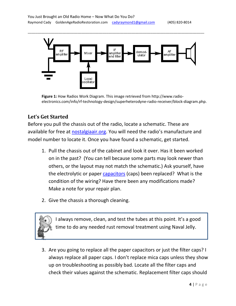
Figure 1: How Radios Work Diagram. This image retrieved from http://www.radio-
electronics.com/info/rf-technology-design/superheterodyne-radio-receiver/block-diagram.php.
Let's Get Started
Before you pull the chassis out of the radio, locate a schematic. These are
available for free at nostalgiaair.org. You will need the radio’s manufacture and
model number to locate it. Once you have found a schematic, get started.
1. Pull the chassis out of the cabinet and look it over. Has it been worked
on inthe past? (You can tell because some parts may look newer than
others, or the layout may not match the schematic.) Ask yourself, have
the electrolytic or paper capacitors (caps) been replaced? What s the
condition of the wiring? Have there been any modifications made?
Make a note for your repair plan.
2. Give the chassis a thorough cleaning.
I always remove, clean, and test the tubes at this point. It's a good
time to do any needed rust removal treatment using Naval Jelly.
3. Are you going to replace all the paper capacitors or just the filter caps? |
always replace all paper caps. | don't replace mica caps unless they show
up on troubleshooting as possibly bad. Locate all the filter caps and
check their values against the schematic. Replacement filter caps should
a|page
You Just Brought an Old Radio Home - Now What Do You Do?
Raymond Cady ~ GoldenAgeRadioRestoration.com cadyraymond1@gmail.com (405) 820-8014,
not be tacked onto the old filters. Ideally, the old terminals should be
cut off and new connections made using a new terminal strip.
4. Controls need to be cleaned and lubed. Check for continuity across
switches. Does the dial cord need restringing? Now’s the time to put on
the new power cord.
5. Connect the radio to the Variac (Variable Voltage Output Transformers)
and let’s power this thing up! (Here's where you hope for the best.)
Does it power up and play or do you have a troubleshooting problem?
If it powers up and plays, congratulations. Now make the case beautiful.
If it doesn’t power up and play, then it has a problem. Let's work
through this and get this radio playing.
Working Through Problems When Your Radio Won't Play
The AC/DC radios (those without transformers) should be (for safety) first
connected to an isolation transformer before powering up an exposed chassis.
These sets can have a hot chassis that can electrocute and kill if proper safety
precautions are not followed. Never touch the chassis with two hands. Always
keep one hand away from the chassis.
You also can plug into the Variac, which is then plugged into the isolation
transformer and you can power up gradually. Now, you can troubleshoot your
radio.
Start with the power supply to make sure it can power the radio. If the power
supply is not working, troubleshoot it as explained in the following instructions.
Once you have a working power supply, you then will troubleshoot the rest of the
radio in backwards order - from the back end (the audio output) to the front end
(the RF receiving/antenna stage.)
S|pPage
You Just Brought an Old Radio Home - Now What Do You Do?
Raymond Cady ~ GoldenAgeRadioRestoration.com cadyraymond1@gmail.com (405) 820-8014,
Troubleshooting the Power Supply
1. Once the chassis is connected to the Variac, power up slowly the Variac
and watch to see if the dial lamp on the radio begins to glow. Raise the
voltage, and then check for glowing in the tubes. Look for smoke and
arcing. If you see, hear or smell either, power off immediately. Check the
chassis to find where the problem is coming from. You will have to fix
that problem before you can move forward.
2. If no power, check for AC voltage at the power cord connections using a
DMM (Digital Multi Meter). You should see around 120v. Check for AC
voltage on each side of the on/off switch while moving the switch on
and off. Power switch failure is very common. The switch will need to be
replaced or rebuilt.
3. A) If this is a radio with a transformer, unplug the radio and put the
probes on each blade of the power cord, and then move the switch to
on. You should see around 10 — 20 ohms for the primary side of the
transformer. Check the high voltage (HV) secondary side by placing one
probe on the rectifier plate and the other on the HV center tap. Expect
around 150 -175 ohms on each plate. Abnormal readings could mean a
shorted or open transformer winding. This means the transformer is bad
and will have to be replaced.
B.) For an AC/DC radio (no transformer), check AC voltage at the On side
of the switch and where the other side of the power cord is connected
to the rectifier.
Troubleshooting the Audio Circuit
1. Quick test for the audio circuit is to inject an audio signal (using a signal
generator) at the grid of the first audio tube. Normal result is a loud
tone heard from the speaker. This point is connected to the middle
terminal lug of the volume control pot (potentiometer — basically the
rotating volume knob) and can be alternately tested by tapping the lug
6lPage
You Just Brought an Old Radio Home - Now What Do You Do?
Raymond Cady ~ GoldenAgeRadioRestoration.com cadyraymond1@gmail.com (405) 820-8014,
with a screw driver. You should loud noise when attempting this. If
there is no sound then there is a problem in the audio output circuit. If
no sound, go to step 2. If there is sound, go to “Troubleshooting the IF
Circuit.”
2. The primary and secondary sides of the output transformer should be
checked for continuity. The primary comes from the output tube and
the secondary runs to the speaker. The primary is a common point of
failure and may be open. If this occurs, the output transformer needs to
be replaced.
3. The speaker voice coil can be checked by connecting test leads to each
side and connecting the other ends to a small battery (I use a AA
battery). When the battery connection is made by tapping on the
battery terminal, you should hear a scratching sound in the speaker if
the voice coil is good. If your speaker is an electrodynamic type, you
need to check the resistance of the field coil. An open field coil is
common in old speakers. A bad field coil means you either must (1)
replace it with a field coil that has similar field coil resistance, or convert
it to a permanent magnet speaker (a modern one), but you will have to
make changes to the radio to accommodate this.
4. If none of this finds the problem, you will have to take individual voltage
readings at each tube pin to isolate the problem. Resistors should be
checked. Normal is + or — 20% of the given value. Usually a resistor that
has drifted way high will be the problem. This is the time when any
suspicious mica caps can be replaced.
Troubleshooting the IF Circuit
1. To check the IF section, inject an RF signal from a signal generator set at
the intermediate frequency at the plate of converter/mixer tube (tube
just before the 1% IF transformer). Normal results will be a loud tone
heard from the speaker.
71Page
You Just Brought an Old Radio Home - Now What Do You Do?
Raymond Cady ~ GoldenAgeRadioRestoration.com cadyraymond1@gmail.com (405) 820-8014,
2. Common problems found include: a bad tube, badly aligned IF
transformer, open coil in an IF transformer, or bad cathode resistor.
Continuity testing of the IF coils can easily be done to eliminate them as.
anissue. An open IF coil requires removal of the transformer from the
radio. A break near one of the terminal lugs can usually be found and
can be repaired by unwinding a turn of wire and re-soldering the
connection.
o Ifthere is a bad tube, replace it.
o Ifthe IF transformer alignment is off, align the trimmers.
o Ifithas a bad coil, replace or repair it.
o Ifithas a bad cathode resister, replace it.
Troubleshooting the Converter (Oscillator and Mixer) Circuits
Most AM circuits use a combination mixer/oscillator tube. The cathode and first
grid are for the oscillator circuit and the RF input grid, screen and plate are for the
mixer circuit.
1. To test the oscillator section, set the radio receiver to 600kc and, using a
signal generator, inject an RF signal of 600k at the mixer grid (RF input
grid). As the receiver is tuned around the 600kc range, a tone should be
heard as the tuner passes through 600kc, if the oscillator is working
properly.
2. If the radio is not oscillating, try another tube or two. Oscillator tubes
are very finicky and a tube can test good on a tester but not oscillate in
the radio.
3. Check the voltage on the oscillator grid (grid 1 of the tube). It must have
negative voltage of at least -7v to oscillate. If voltage is 0, check the
oscillator coil for continuity and be suspicious of the cathode-to-grid
resistor.
4. Problems in the mixer circuit are usually detected by checking pin
voltages. An abnormal reading will lead to the part of the circuit that is
not functioning properly.
8|page
You Just Brought an Old Radio Home - Now What Do You Do?
Raymond Cady ~ GoldenAgeRadioRestoration.com cadyraymond1@gmail.com (405) 820-8014,
Troubleshooting RF Input
Problems with RF input usually involve an antenna problem.
1. To test for an antenna problem, inject an RF signal at the antenna input.
You should hear a load, clear tone. If you do not hear a tone, bypass the
antenna by injecting the signal directly to the tuning capacitor. If the
radio plays, the problem is in the antenna circuit.
2. Oscillation or poor quality sound may be due to improper shielding
(tube shields need to be grounded) or poor ground connections in the
chassis. Rivet grounding connections get loose and lose contact. Any
poor or cold solder joints should be re-soldered. A spooge stick (basically
a non-conductive stick you can use to tap items in the radio while
testing for issues) can be tapped on the ground points and solder joints
to see if they cause any noises or make things better.
Now that you have gone through your radio and got it working, it’s time to mount
the chassis back into the radio. Turn it on again. It's not completely unheard of for
a radio that was working while the chassis sat on your workbench to stop working
once you put the chassis back in. Don't be discouraged, just pull it back out and
take another look at it. It might be as simple as a loose antenna connection that
was knocked free when putting the chassis back into its cabinet.
Don't get discouraged. If worse comes to worse, you can always have someone
else take a look at it for you. And if nothing else, shine up and make beautiful the
cabinet. It still will look great in your collection.
9lpage
RADIO-BUILDER'S HANDBOOK
SCHEMATIC SYMBOLS USED IN RADIO
Thie symbels below are standard in radio, TV
and clectronics diagrams.
curved wire crosover and dotted connection fs
preferred.
The symbol for & ground point may indicate
actual connection 16 the métal chasis, or & cor
i s el b
S M e e
RON CORE. °° ° Oa SWITCH
ar CRYSTAL
e | 4
e | 31 s
gt
ThansromeR | o\ o ruse
—@— ruor e
R
s
amssrons| I caneron mfiq ElecTroommame
4 ONE CELL OR Apwusrs
— g | K F SR e
e —
T e 2= o
P e A
e | o o .
[ 8= ] 2
2 o s
[y L= oo ¥
10
ééfi’f%fi@ o §
Swihes MeshTouth Clip Crocadile Clp n..m. Phone rinteg
| Chart of Radio Symbols
—
aewu g we O
comecren | —4— A
? oo Silte | & | yacuum TUBES
ohiEE -
S| = 1922 — 1935
v :{wwcn Ty R * P
crouno et chj; s,
Ry cratobe | ¥
= SNGLE - + [ Two rement q
xeo o B
convENSER e aow | %] s
SWITCH o s DETECTION | 4 r
Coudinsi sovngmon| 2 Jo| B G | e
“GANGED" (rmoper) | * o
- screen N4
% coxorusea sarreaes e,
(BER g Cremopes |20t
PHONO —u
Beeo | R coxe PICKUP / e |
e cons — e |udoh
w(v;\.ctn PHONOGRAPH "1'.::::‘
TRANSFORMER) | e - rf “
MAGNETIC g %
[ v | & soven
o pewrase
AUDIO. OCTAL BASE SOCKET
fi SR west | [ Amvan
s
A%
ot =
BcaliS FoR DETAILS OF CoNECrIONS
Pusn-puLL e ™ =R ] | see MrRs. TUBE MANUALS
Takns- ueso NEVER GUESS /
e, s oo
L
FixeD posT TYPICAL MODERN TUBES
W
Jhcx GRIO. DIODE~ TRIODE
YRR
e secerma| —(@)— P
B
a0 MULTI-GRID TUBE
e e % e aaios ane
s 2 o
(PoTenTI- vourmereR | @ | - [/ USUALLY BEING THAT
Pty L S o